
SMD Jumper Cable
1. Product Application Scope and Advantages
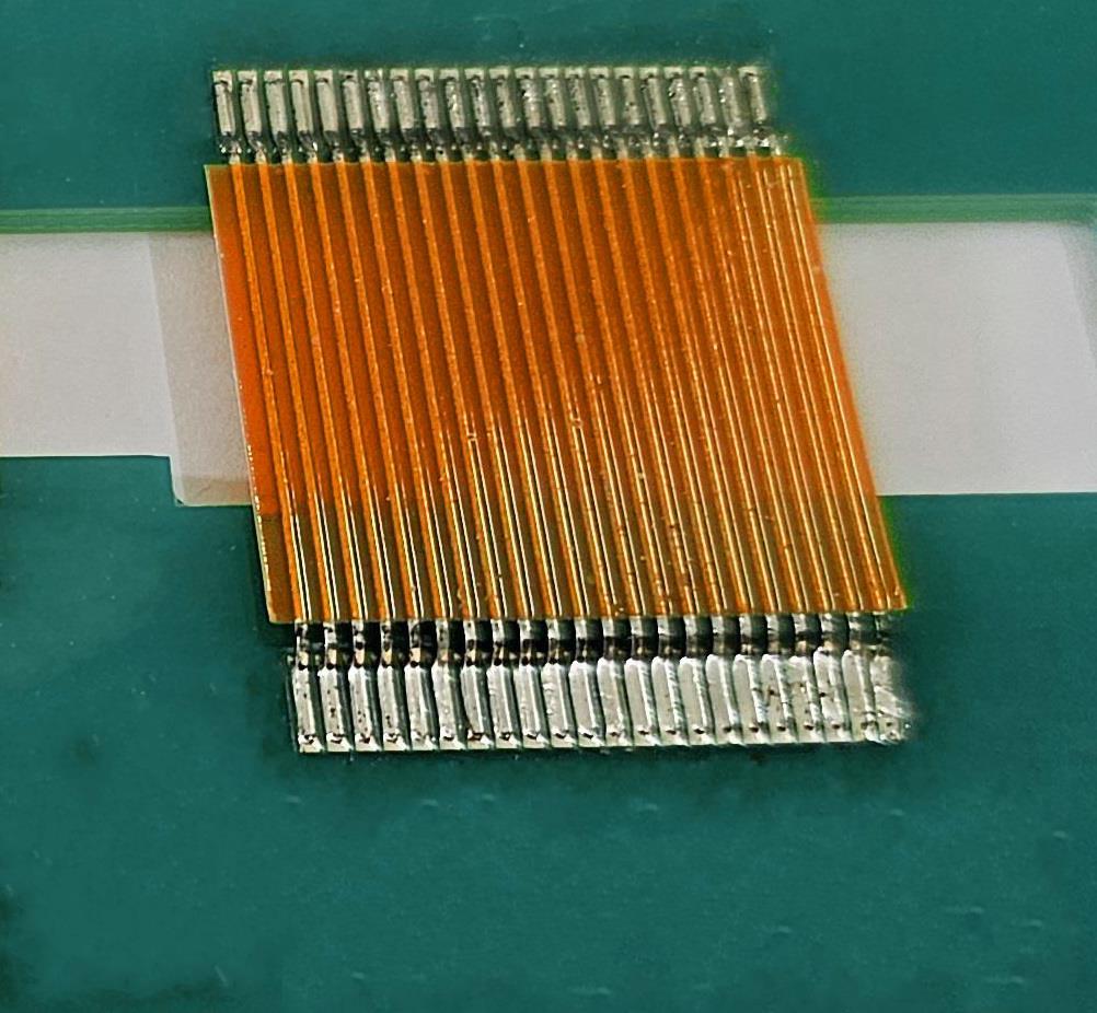
SMD Jumper Cable
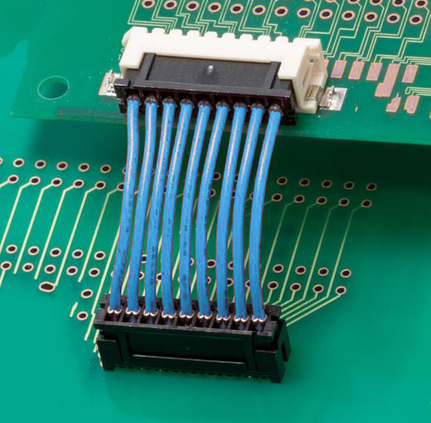
Wiring Harness
Our SMD jumper cable is used for circuit connections between PCBs. The SMD jumper cable is significantly superior to traditional wiring harnesses in many aspects:
-
1-1. Cost-saving and supplier consolidation.
There is no need to assemble crimp terminals and plugs at the cable ends, nor is there a need to mount socket connectors on the PCB to interface with wiring harness plugs. -
1-2. More reliable connections.
By directly soldering the conductor ends of the SMD jumper cable as soldering pins on the PCB, eliminating multiple intermediate connection points in traditional wiring harnesses like "board-end socket - wiring harness plug - crimp terminal - cable - crimp terminal - wiring harness plug - board-end socket," greatly reduces the occurrence of circuit breaks or poor contacts. -
1-3. Small size, low height, flexible wire spacing.
The minimum cable pitch can be down to 0.3mm; even each pitch can be customized with completely different pitch; suitable for narrow internal spaces or PCB layouts. Of course, it can also be customized with larger conductor diameters and cable pitch to meet customer requirements for high current and voltage designs. -
1-4. Fully automated assembly.
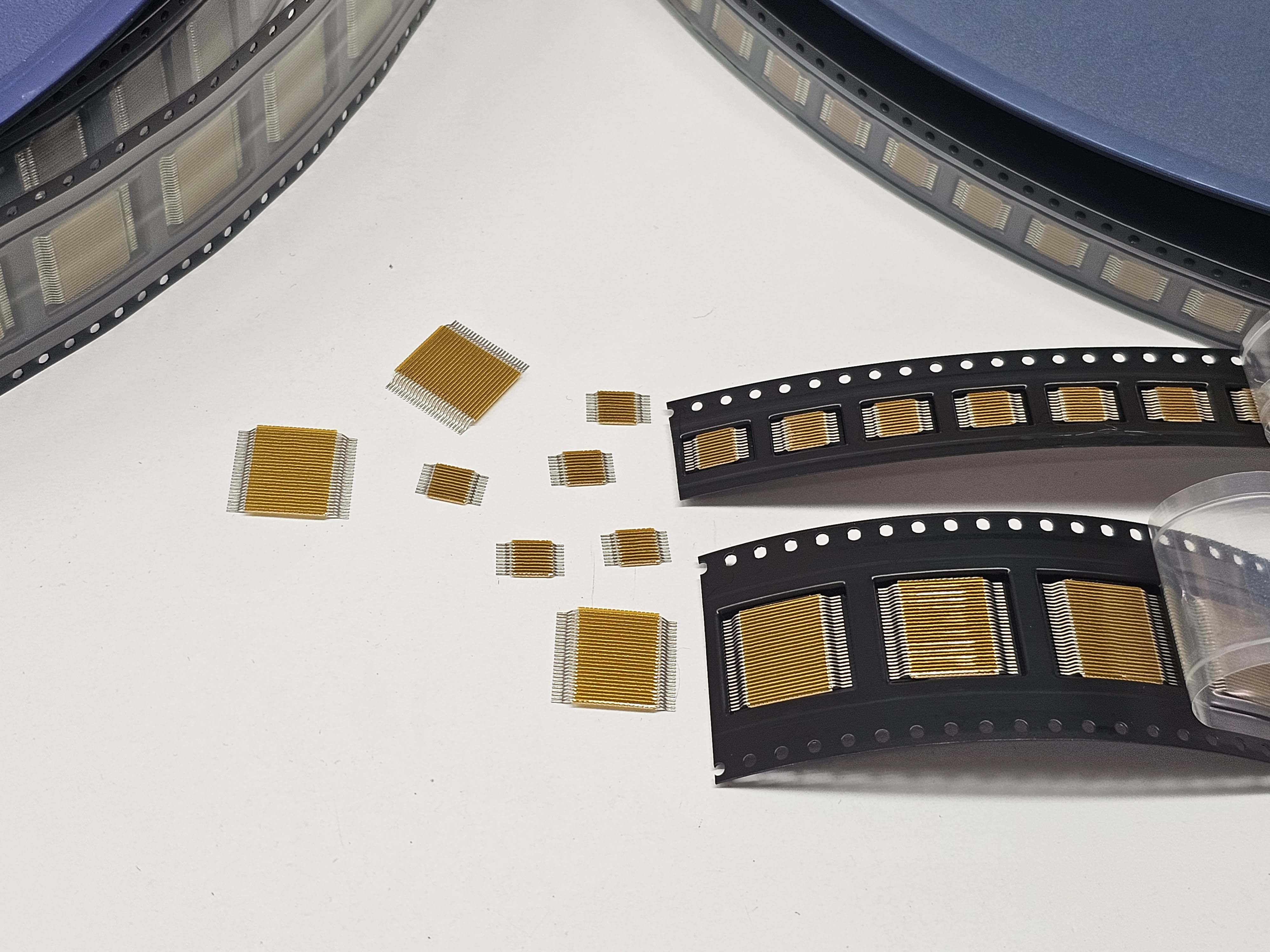
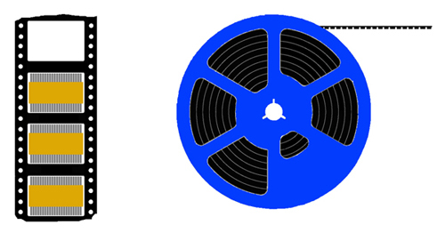
SMD jumper cables are packaged in SMD tape-reels, picked and placed using SMD automated pick-and-place machines, and then mounted using reflow soldering.
2. Tape-Reel Packaging
3. Board-to-Board Connection Methods
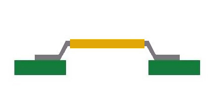
Board to board interconnection
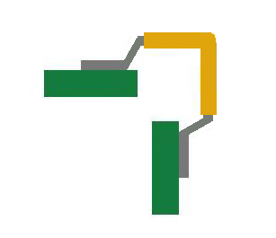
90 degrees board to board interconnection
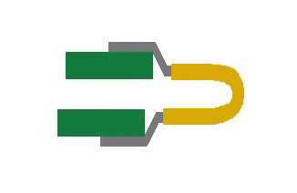
180 degrees board to board interconnection
4. Product Specification
| 4.1 Cable pitch | 0.3mm, 0.35mm, 0.5mm, 0.8mm, 0.93mm, 1.0mm, 1.25mm, 1.27mm, 1.5mm, 2.0mm, 2.50mm, 2.54mm. Customization available for other pitch not listed above. |
| 4.2 Number of Conductors | From 2 to 40 pins. |
| 4.3 Conductor Size | Flat conductors or round conductors (conductor size designed based on rated current). |
| 4.4 Length Range | Minimum length 4mm, common lengths 5.5mm, 8.5mm, 12mm, 15.2mm, 20mm, 25.4mm; customization available for other lengths. |
| 4.5 Insulation Material | The most commonly used material is Kapton (polyimide). |
| 4.6 Conductor (Soldering Pin) Material | Tin-plated copper wire. |
5. Product Characteristics (Based on the most commonly used specifications as examples)
| Parameter | 0.5mm Pitch | 0.93mm Pitch |
|---|---|---|
| Wire Gauge | 30AWG | 28AWG |
| Min. Bend Radius | 1mm | 1mm |
| Current Rating | 1.0A | 1.5A |
| Voltage Rating | 200V | 200V |
| Min. Breakdown Voltage at 1 min. | 1000V | 1000V |
| Insulation Resistance (at DC500V) | 2×10¹²Ω | 2×10¹²Ω |
| Soldering Temperature (for reflow soldering) | 300℃/60sec | 300℃/60sec |
| Operating Temperature - Standard Version | -40℃ to +150℃ | -40℃ to +150℃ |
| Operating Temperature - High Tg Version | -40℃ to +170℃ | -40℃ to +170℃ |